Bernstein-Vazirani Algorithm
Another toy problem
Much like the Deutsch-Jozsa problem, the Bernstein-Vazirani problem is a toy problem in which you are given a black box function that you want to learn about with as few iterations as possible. Just like before, the black box function takes in \(n\) bits of input and outputs a single bit:
public bool BlackBox(bit[] Input)
However, in this case instead of having a constant or balanced function, we know that the oracle function, \(f\), performs a bitwise dot product of the input bit string \(x=x_0x_1...x_{n-1}\) with some fixed (albeit unknown) bit string \(s=s_0s_1...s_{n-1}\). That is \(\(f(x)=(s_0x_0)\oplus (s_1x_1)\oplus...\oplus(s_{n-1}x_{n-1}).\)\)
The goal here is to find out the value of the mystery string, \(s\), with as few iterations of the function as possible. Classically, we know that we can figure out \(s\) with \(n\) iterations of the function. We can probe the function by inputing a string with the \(i\) -th bit set to 1 and all other bits set to 0. Then the function will output the value of \(s_i\). Since we get one bit of information per iteration of the function, we can't figure out \(s\) in less than \(n\) iterations. Using a quantum algorithm, however, we can figure out \(s\) in one iteration!
Implementing the Oracle
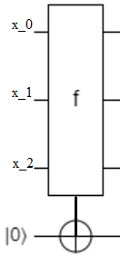
If we were told to classically implement such a function, \(f\), and were given the string \(s\), how would we do it? To be more specific, we are given an input register consisting of \(n\) bits initilized to the values of the bits of an input \(x\) and an output register consting of one bit initialized to 0. The goal is for us to set the output bit to the value of \(f(x)\). Essentially, this looks like
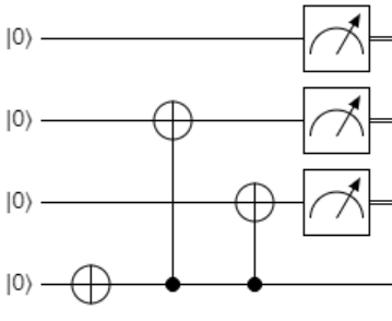
First, we could notice that if a bit of \(s\), \(s_i\), was zero than the value of \(x_i\) has no impact on the output of \(f\). Thus, we can leave these bits in the register alone. On the other hand, if \(s_i=1\), then toggling \(x_i\) between 0 and 1 flips the value of the resulting \(f(x)\). We can implement this by adding a CNOT gate for every non-zero bit, \(s_i\), which will have the \(i\) -th bit in the input register as a control and the output bit as a target.
As an example, if \(s=011\), then an implementation of \(f\) would look like
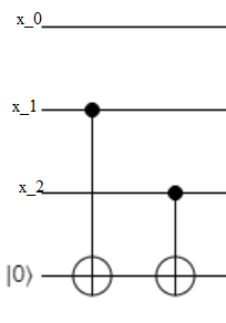
This serves just fine as a quantum operation as well. Note that in the actual problem the oracle's mystery string is unknown. But we can rest assured that it behaves equivilantely to a circuit with a bunch of CNOT gates with certain input bits as controls and the output bit as the target. Our goal then is to find out which input bits control a CNOT gate and which ones don't.
Phase kickback (again)
The quantum algorithm that solves this problem is pretty similar to the one that solves the Deutsch-Jozsa problem: flip the output bit to the 1 state, apply \(H\) gates to all qubits (this time including the output qubit), apply the oracle, apply the \(H\) gates again, and finally measure the qubits. This algorithm helps demonstrate an interesting way of interpreting phase kickback: applying Hadamard gates before and after a CNOT gate swaps the control and target of CNOT gate.
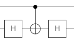
Indeed, if we could somehow flip all the CNOT gates in the earlier diagram upside down, then an output qubit in the 1 state would set all the CNOT gates off so that an input register initialized to \(x=00...0\) would become the mystery string \(s\). To understand how phase kickback does this we first have to verify that the following matrices are equal: \(HXH\) and \(Z\). Of cource, we can just do the multiplication of the 2-by-2 matrices to see this directly. However, we could also prove that \(HXH=Z\) by showing that the two quantum operations have the same effect on basis states \(\ket{0}\) and \(\ket{1}\). If we first apply an \(H\) gate to the two states, we get a \(\ket{+}\) and \(\ket{-}\) state. Applying an \(X\) to both states yields \(\ket{+}\) and \(-\ket{-}\). Finally, applying another \(H\) yields \(\ket{0}\) and \(-\ket{1}\), the same effect as just applying the phase gate \(Z\). This also shows that a CNOT gate with Hadamard gates around the target has equivilant behaviour to a CZ gate:
is equivilant to
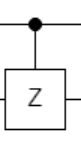
This is because if the control bit is 1, then an \(HXH=Z\) gate is applied to the target, while if the control bit is 0, then an \(HH=I\) gate is applied instead.
Recall, from the controlled gates section that the target and control of a CZ gate are interchangeable. Thus, if the output bit is set to 1 before encountering the Hadamard gates of our circuit it will set of the CZ gates. These will act on the input register bits corresponding to non-zero \(s_i\). Since Hadamard gates where applied to all the input register qubits, they will all be in the \(\ket{+}\) state. Those qubits corresponding to \(s_i=0\) will remain unaffected (there is no controlled gate connecting them to the output qubit), while the qubits correspodning to \(s_i=1\) will be targeted by an "effective" CZ gate which will make change them to the \(\ket{-}\) state.
Finally, another round of Hadamard gates will turn the \(\ket{+}\) states in the input register into \(\ket{0}\) and will turn the \(\ket{-}\) states in the input register into \(\ket{1}\). Thus, at the time of measurement the input register has the value of \(s\) encoded in its qubits and measuring it reveals \(s\).
Applying this to our example with \(s=011\), we are attempting to run the quantum circuit diagram
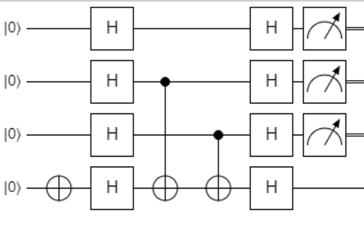
which is equivilant to
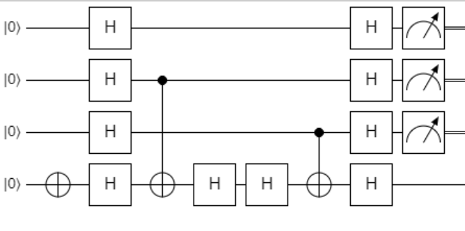
since \(H^2=I\). This is then equivilant to
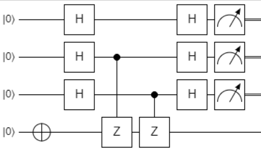
since \(HXH=Z\). Then using the interchangibility of control and target of the \(Z\) gate
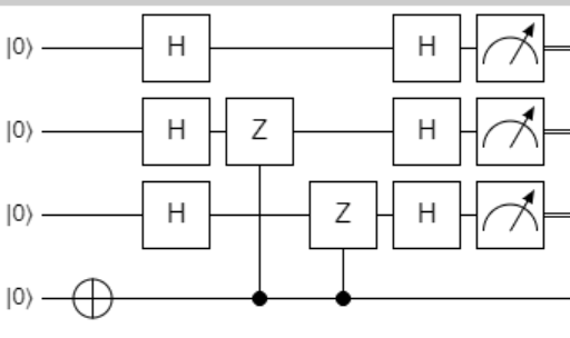
which is finally equivilant to
since \(HZH=X\) (prove this for yourself as an exercise) and \(H^2=I\). Understanding why the above algorithm works uses something called a quantum circuit diagram equivilance argument. This is sometimes a great tool to get around having to keep track of states in a complicated superposition with many amplitudes. We summarize the algorithm as follows.
Implementation
- Apply X to the output qubit, so it is in the \(\ket{1}\) state.
- Apply H to all of the qubits (including output).
- Run the oracle on the input register and output qubit (the oracle should perform a CNOT on the output).
- Apply H to all of the qubits.
- Measure all of the input qubits to find \(s\).